INSTRUCTIONS FOR THE FORMATION OF MEASUREMENT POINTS FOR EMISSION MEASUREMENT IN ACCORDANCE WITH THE VALID INTERNATIONAL STANDARD EN 15259: 2010
Determining the position of the sampling plane:
Sampling level (2) it must be as far away as possible from the last obstruction (change of flow direction, current cross section or other cause of waste gas turbulence), in order to perform sampling in the least turbulent (“turbulent”) waste gas streams (4) . For this reason, the sampling plane is placed in a zone whose beginning and end are at least 5 hydraulic diameters (ødh) away from the last obstruction, ie the end of the flue (5) thus generally fulfilling the requirement for homogeneous conditions.
The hydraulic diameter is for flue ducts:
² circular cross-section – equal to the diameter of the sampling plane;
² square section – equal to the side of the square;
² rectangular cross section – dn = 2) (a ∙ b) / (a + b) ;
² other cross-sectional shapes, calculated by the formula d = 4xAs / ls , where As is the area of the sampling plane, and ls is its circumference.
In case the sampling plane is placed in the part of the flue duct whose end is not the end of the duct, but some obstruction (eg curve) it is allowed that from the sampling plane to it there are only 2 hydraulic diameter.
As a rule, the sampling plane is positioned in the vertical part of the channel, and only if that is not possible, in the horizontal part.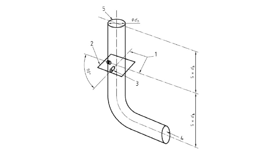
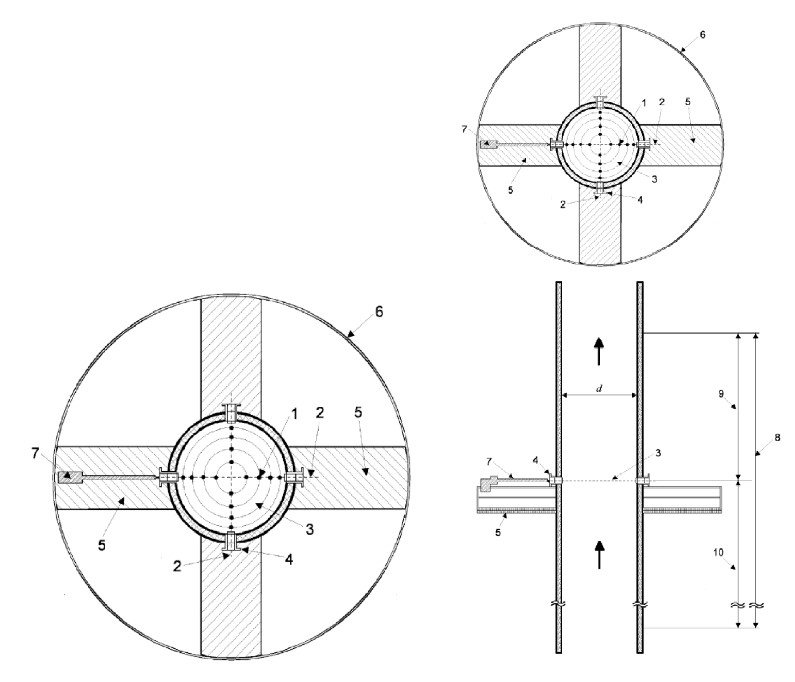
Figure 1.A Position of sampling planes and access openings on the circular flue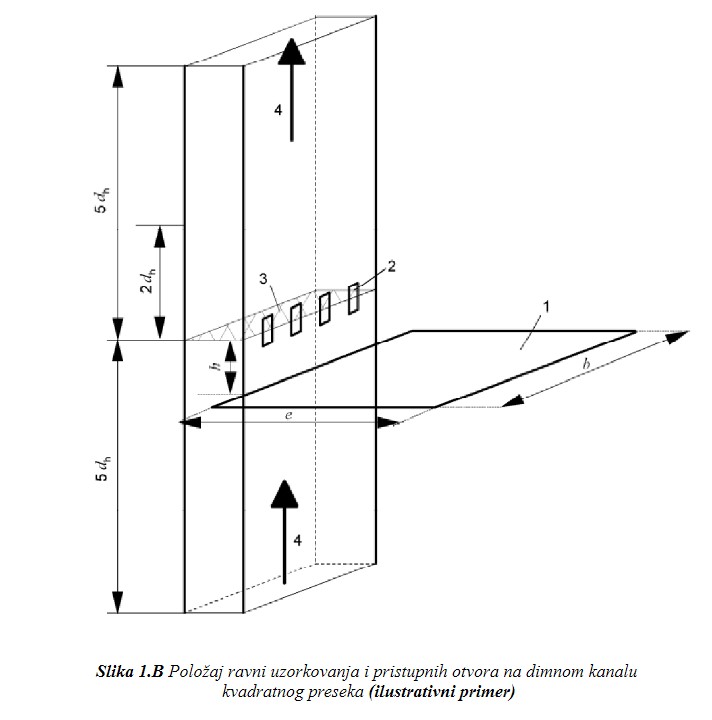
Determining the number of sampling lines and the position of access openings:
For channels of circular cross-section, the number of openings is almost always 2 and they are positioned at an angle of 90 degrees (with the exception of emitters whose diameter is less than 350 mm), as shown in Figure 1.
For channels of rectangular cross-section, the required number and position of access openings are determined separately, and in that case it is necessary to obtain a special instruction from an expert authorized organization for emission measurement for each specific case.
Making an access opening:
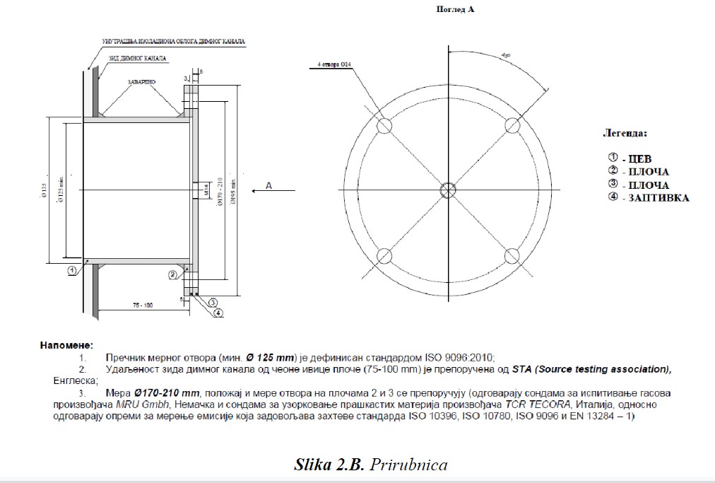
The access opening is equipped with a flange and looks like in Figure 2:
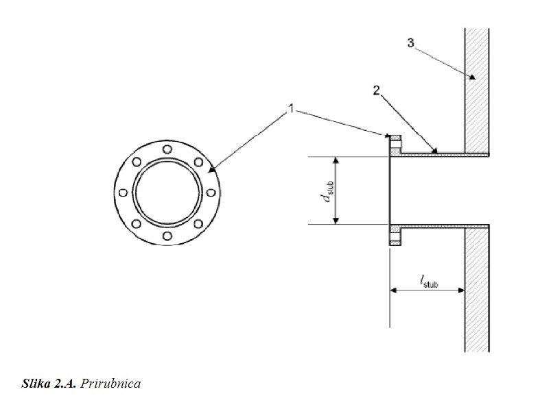
1. flange with inner diameter dstub = 125 mm
2. pipe with inner diameter dstub = 125 mm and minimum length lstub = 75 mm from the flue
3. flue wall
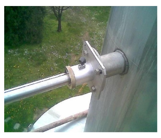
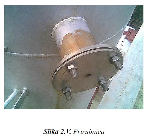
Installation of an access opening for emission measurement
The access opening is mounted at the location of the sampling plane whose position is determined as described. The opening must be installed in such a way that:
- For circular sections TWO access openings are mounted along the circumference of the flue at an angle of 90 °;
- For rectangular cross-sections, the openings are mounted according to the special instructions of the expert authorized organization for emission measurement;
- A length probe will be placed through the openings 2 m , so it is necessary to provide a minimum manipulative space of 2.2 m.
After mounting the opening, it is closed with a suitable blind flange. An opening for measuring gaseous combustion products with a thread is placed in the center of the blind flange M14 (It can also be an opening with an externally welded nut M14 ).
Legend:
- measuring point
- measuring line
- measurement plane
- measuring hole
- free surface
- area of measurement
- manual sampling
- measurement section
- output section
- entrance section
Symbols:
d – inner diameter of the flue